This document describes the serial port communication protocol used by the Belkin "Universal UPS" and compatible models.
Summary
This document describes the serial port communication protocol used by the Belkin "Universal UPS". This protocol is known to work with the F6C800-UNV and F6C120-UNV models, and presumably also works with the other Universal UPS models, such as the F6C500-UNV, F6C100-UNV, and so forth. Note that this protocol does not work with the Belkin "Home Office" series, nor with the "Regulator Pro" series. For some pointers to information on other Belkin protocols, see Note: Other Belkin Protocols below.
General Information
I bought a Belkin "Universal UPS" because, next to APC, Belkin systems are among the most widely available in stores, at least in Canada. For instance, they are available from Radio Shack, Target, Office Depot, etc.
On the surface, Belkin seems Linux-friendly, because they provide a Linux version of their "Bulldog Plus" UPS management software. This software is not included on the CD Rom which ships with the UPS, but one can download it from Belkin’s website.
However, unfortunately, the Bulldog Plus software is not as useful as it might seem. It has many bugs (see Bugs in Bulldog), and it cannot be configured to allow an unsupervised recovery (the user must press the front panel button to restart the UPS after a power failure).
Since the specifications of the protocol were not available, I decided to do some detective work and to decipher the protocol myself. The results are described in this document. The information reported here is necessarily incomplete, but it seems that the most important aspects of the protocol have been covered.
Unfortunately, there is one serious problem with the "Universal UPS" firmware: there is no command which causes the UPS to go into "soft shutdown" mode, which means, to shut off the load until AC power returns. This makes unsupervised recovery from power failures tricky and awkward (see Soft Shutdown Workaround for a suggested solution).
On balance, the Belkin UPS works fine, but the lack of a "soft shutdown" command is annoying. If you are thinking about buying a UPS, I think currently APC is a better choice than Belkin at approximately the same price. Maybe Belkin will come up with an improved version of their firmware in the future.
Note: Other Belkin Protocols
Belkin uses different communication protocols for different UPS hardware. Belkin’s "Bulldog Plus" software apparently knows several of these protocols, and automatically figures out which one to use based on the responses it receives from the UPS. I know of the following protocols. The "NUT Driver" entries below refer to the Network UPS Tools software.
- Universal UPS and compatible
-
Typical message:
0x7e 03 02 01 00 84Described in:
this document
NUT Driver:
belkinunv
Product code:
F6C800-UNV, F6C120-UNV etc.
Date:
2004
- Home Office UPS and compatible
-
Typical message:
None (dumb UPS only?)
NUT Driver:
genericups, with
upstype=7.Product code:
F6H350-SER, F6H500-SER etc.
Date:
2003
- Regulator pro Gold series and compatible
-
Typical message:
~00P003MNUDescribed in:
NUT Driver:
belkin
Date:
ca. 2000
- Older Belkin USVs, compatible with Trust425&625 UPS
-
Typical message:
0x01Described in:
ups-trust425+625.txt by Peter Bieringer <pb@bieringer.de> (distributed with nut-0.41.2)
NUT Driver:
powercom (?)
Date:
ca. 1999
The following information was provided by Dean Gibson about the "Home Office" models:
Only the "Universal UPS" is described in this document.
Soft Shutdown Workaround
The main problem with the Belkin Universal UPS is that there appears to be no software way to put the UPS into "soft shutdown" mode. This makes unsupervised recovery from power failures tricky. There is a reliable workaround, as described in this section, but it is awkward. One must conclude that Belkin’s engineers do not understand the purpose of a UPS very well, at least as it relates to unsupervised recovery.
To understand the issue, consider what should normally happen to an unsupervised computer (such as a server) during a power failure:
-
The AC power fails, and the UPS goes on battery mode.
-
When the battery gets low, the computer enters its normal shutdown sequence.
-
As the very last step of the shutdown process, the computer signals the UPS to do a "soft shutdown", i.e., to turn its load off and await AC power. This kills the computer’s power supply, and thus the computer is turned off.
-
When the power comes back on, the UPS load comes back on, restoring the computer’s power supply, and thus causing the computer to reboot. (Note that there is a BIOS setting by which one can tell the computer to reboot after power loss).
Moreover, if AC power happens to be restored during step 2, the UPS should still turn its load off briefly in step 3, to allow the computer to reboot.
The problem with the Belkin UPS is that step 3 is not possible. One cannot signal the UPS to do a "soft shutdown". One can only signal it to do a "final shutdown", which means, the UPS stays off even if the power returns. This leaves the entire system in a state where a human needs to press the button on the UPS front panel to restart the system.
There is one way around this problem. Namely, the UPS will enter "soft shutdown" mode when its batteries run out. Thus, it is possible to handle a power failure as follows:
-
The AC power fails, and the UPS goes on battery mode.
-
When the battery gets low, the computer enters its normal shutdown sequence.
-
As the very last step of the shutdown process, we call a special program which does nothing but to monitor the UPS status.
-
If the AC power comes back on before the batteries run out, our program notices this and causes the computer to reboot.
-
If the batteries run out before the AC power comes back on, then the UPS shuts off its load, thereby killing the computer’s power supply. The UPS is now in "soft shutdown" mode and everything will reboot when the power comes back on.
The major practical drawback of this solution is that the battery level is guaranteed to be 0% when the system reboots. Thus, if another power failure happens before the batteries are recharged, the system will crash with not enough warning to do an orderly shutdown. We can solve this problem by adding another special purpose program to the startup script, before anything is written to the hard disks, which monitors the UPS and waits for the battery level to reach a minimum amount before allowing the boot process to resume. This ensures that the system is in a safe state, should the power fail again.
I have implemented the required functionality as part of the NUT belkinunv driver.
The belkinunv driver can be used as a standalone program by calling it with the "-x wait" option.
When called with this option, the driver does not fork into the background, but simply connects to the UPS and waits for AC power to be restored.
The intention is that one puts commands such as the following as the last part of the computer’s shutdown script:
# NEAR END OF SHUTDOWN SCRIPT:
# if shutdown was caused by UPS, perform Belkin UPS workaround.
if [ -f /etc/killpower ] ; then
    echo "Waiting for AC power, or for UPS batteries to run out..."
    /usr/bin/belkinunv -x wait /dev/ttyS1

    # we get here if the power came back on. Reboot.
    echo "Power is back. Rebooting..."
    reboot
fi
In addition, when called with the "-x wait=level" option, the belkinunv driver waits for the battery charge to reach the specified level.
This can be used in a startup script as follows.
Put this before any disks are mounted read/write, and before any file system integrity checks, so that the system is in a safe state.
# NEAR BEGINNING OF STARTUP SCRIPT:
# if we are recovering from a power failure, wait for the UPS to
# charge to a comfortable level before writing anything to disk
if [ -f /etc/killpower ] ; then
    echo "Waiting for UPS battery charge to reach 60%..."
    /usr/bin/belkinunv -x wait=60 -x nohang /dev/ttyS1
fi
Here, the "-x nohang" option ensures that the computer will boot properly in case the UPS is no longer attached.
There might be many reasons to remove the UPS during a power failure, for instance, you take your computer to a friend’s house, or you attach it to a generator, or whatever.
Giving the "-x nohang" option ensures that your computer is always bootable.
For a detailed description of the "-x wait" and related options, please see the belkinunv(8) man page.
Description of the Protocol
Opening the serial communication link
The serial port parameters are: 2400 baud, 8 bits, 1 stop bit, no parity.
More precisely, the following parameters are used: B2400 | CS8 | CREAD | HUPCL | CLOCAL.
In order to get the UPS to switch to "smart" mode, one first needs to set RTS and drop DTR for at least 0.25 seconds (RTS and DTR refer to two specific pins in the 9-pin serial connector). This signals the UPS to switch to serial mode. Without this step, there will be no serial communication possible. In experimenting with my own UPS, I found that 0.25 seconds is the minimum time required for the UPS to react; however, the time required may differ for different UPS hardware. The Bulldog software waits 1 second, so this is probably a safe bet.
After this, flush any unread garbage bytes from the serial port. Thereafter, simply communicate with the port via usual "read" and "write" operations.
The following C procedure shows exactly how the serial port should be opened and prepared:
#include <fcntl.h>
#include <sys/ioctl.h>
#include <string.h>
#include <errno.h>
#include <termios.h>
#include <unistd.h>

/* Open and prepare a serial port for communication with a Belkin
   Universal UPS. DEVICE is the name of the serial port. It will be
   opened in blocking read/write mode, and the appropriate
   communications parameters will be set. The device will also be
   sent a special signal (clear DTR, set RTS) to cause the UPS to
   switch from "dumb" to "smart" mode, and any pending data (=garbage)
   will be discarded. After this call, the device is ready for reading
   and writing via read(2) and write(2). Return a valid file
   descriptor on success, or else -1 with errno set. */

int belkin_open_tty(char *device) {
  int fd;
  struct termios tios;
  struct flock flock;
  char buf[128];
  const int tiocm_dtr = TIOCM_DTR;
  const int tiocm_rts = TIOCM_RTS;
  int r;

  /* open the device */
  fd = open(device, O_RDWR | O_NONBLOCK);
  if (fd == -1) {
    return -1;
  }

  /* set communications parameters: 2400 baud, 8 bits, 1 stop bit, no
     parity, enable reading, hang up when done, ignore modem control
     lines. */
  memset(&tios, 0, sizeof(tios));
  tios.c_cflag = B2400 | CS8 | CREAD | HUPCL | CLOCAL;
  tios.c_cc[VMIN] = 1;
  tios.c_cc[VTIME] = 0;
  r = tcsetattr(fd, TCSANOW, &tios);
  if (r == -1) {
    close(fd);
    return -1;
  }

  /* signal the UPS to enter "smart" mode. This is done by setting RTS
     and dropping DTR for at least 0.25 seconds. RTS and DTR refer to
     two specific pins in the 9-pin serial connector. Note: this must
     be done for at least 0.25 seconds for the UPS to react. */
  r = ioctl(fd, TIOCMBIC, &tiocm_dtr);
  if (r == -1) {
    close(fd);
    return -1;
  }
  r = ioctl(fd, TIOCMBIS, &tiocm_rts);
  if (r == -1) {
    close(fd);
    return -1;
  }

  /* flush both directions of serial port: throw away all data in
     transit */
  r = tcflush(fd, TCIOFLUSH);
  if (r == -1) {
    close(fd);
    return -1;
  }

  /* lock the port */
  memset(&flock, 0, sizeof(flock));
  flock.l_type = F_RDLCK;
  r = fcntl(fd, F_SETLK, &flock);
  if (r == -1) {
    close(fd);
    return -1;
  }

  /* sleep at least 0.25 seconds for the UPS to wake up. Belkin's own
     software sleeps 1 second, so that's what we do, too. */
  usleep(1000000);

  /* flush incoming data again, and read any remaining garbage
     bytes. There should not be any. */
  r = tcflush(fd, TCIFLUSH);
  if (r == -1) {
    close(fd);
    return -1;
  }

  r = read(fd, buf, 127);
  if (r == -1 && errno != EAGAIN) {
    close(fd);
    return -1;
  }

  /* finally, switch to blocking i/o, so that future read/write calls
     will read or write at least one byte */

  r = fcntl(fd, F_SETFL, 0);   /* clear O_NONBLOCK */
  if (r == -1 && errno != EAGAIN) {
    close(fd);
    return -1;
  }

  return fd;
}
Structure of messages
The same basic format is used for messages from the computer to the UPS ("commands") and from the UPS to the computers ("responses"). Communication takes place as a sequence of command/response pairs. Communication is always initiated by the computer, and the UPS reacts to each command by sending a single, matching, response.
The format of all messages is:
| Header | Type | Length | Register ID | Data | Checksum |
|---|---|---|---|---|---|
1 byte |
1 byte |
1 byte |
1 byte |
variable |
1 byte |
The message fields are explained as follows:
|
Header
|
The literal byte |
||||||||||
|
Type
|
There are five possible message types:
|
||||||||||
|
Length
|
The number of bytes in the Data field, plus 1. Equivalently, the length of the entire message, minus 4. |
||||||||||
|
Register ID
|
The number of the register to be read or written. |
||||||||||
|
Data
|
The argument of the message. The precise meaning depends on the type of message.
|
||||||||||
|
Checksum
|
The checksum for this message.
It equals the sum of all previous bytes of the message (including the initial |
Format of responses
Each command (computer to UPS) is followed by a single response (UPS to computer).
A read command (type=3) is normally followed by a read response (type=5), or sometimes by an error response (type=1).
A write command (type=4) is normally followed by a write response (type=2), or sometimes by an error response (type=1).
The Register ID field of the response is identical to the Register ID field of the command being responded to. Moreover, the Data field of the response is identical to the Data field of the command being responded to, in case of an error response or a write response. In case of a read response, the Data field is of course the value being read.
An error response is only sent if the corresponding command was well-formed (including a correct checksum), but cannot be obeyed for some reason (e.g., the corresponding register is not implemented). Ill-formed commands are silently ignored.
Examples
Reading a 1-byte register
|
Command
|
read register |
|
Response
|
register |
Reading a 2-byte register
|
Command
|
read register |
|
Response
|
register |
Reading a string register
|
Command
|
read register |
|
Response
|
register |
Reading a non-existent register
|
Command
|
read register |
|
Response
|
error: cannot read register |
Writing to a register
|
Command
|
write |
|
Response
|
written successfully |
Writing to a non-existent register
|
Command
|
write |
|
Response
|
error: cannot write to register |
Individual UPS registers
The UPS has a number of internal registers, which can be read and/or written. Some registers are read-only. There either hold hard-coded values (such as the UPS model name or nominal voltage rating), or they describe the state of the UPS, such as the current battery voltage or whether certain events have occurred. Some other registers can be read and written. These registers control or configure aspects of the UPS’s behavior, such as its voltage sensitivity, or whether the audible alarm is enabled. In some cases, setting the value of a writable register triggers an event, such as a battery self-test or a UPS shutdown.
Each register is identified by a unique number, the register ID. We always write register ID’s as hexadecimal values.
Registers can hold different types of data. Some registers hold a 1-byte integer, others hold a 2-byte integer, and others hold a variable length string.
Some registers are read only once (during startup) by the Bulldog software, and thereafter ignored. These registers are marked "startup" in the list below. All other registers are read periodically.
We now describe the individual registers:
| Reg.ID | Name | Data | Flags | Typical Value | Description | ||||||||
|---|---|---|---|---|---|---|---|---|---|---|---|---|---|
|
unknown / does not exist |
n/a |
n/a |
n/a |
This register does not really exist.
It is written by the linux driver when the user requests to set the voltage sensitivity.
However, this is a bug and the UPS responds with an error message.
The Windows driver correctly writes register |
||||||||
|
voltage rating |
1 byte |
|
|
The nominal voltage in V.
In North America, this is |
||||||||
|
frequency rating |
1 byte |
|
|
The nominal AC frequency in Hz.
In North America, this is |
||||||||
|
power rating |
2 bytes |
|
|
The nominal power rating in VA.
For a 800VA UPS, this is |
||||||||
|
battery voltage rating |
1 byte |
|
|
The nominal battery voltage in V.
For my system, this is |
||||||||
|
unknown |
1 byte |
|
|
I don’t know the function of this register.
On my system, it takes value |
||||||||
|
low transfer voltage |
2 bytes |
|
|
I am not entirely sure about the meaning of registers The only way to test whether these "transfer points" actually work would be to vary the UPS input voltage and observe what happens.
I don’t have equipment to do this.
Ditto for register |
||||||||
|
low transfer voltage upper bound |
2 bytes |
|
|
|||||||||
|
low transfer voltage lower bound |
2 bytes |
|
|
|||||||||
|
high transfer voltage |
2 bytes |
|
|
|||||||||
|
high transfer voltage upper bound |
2 bytes |
|
|
|||||||||
|
high transfer voltage lower bound |
2 bytes |
|
|
|||||||||
|
voltage sensitivity |
1 byte |
|
|
The voltage sensitivity can be read and written.
Admissible values are |
||||||||
|
UPS model |
string |
|
The UPS model name as a sequence of ASCII characters, not null-terminated.
For my system, registers |
|||||||||
|
UPS model |
string |
|
||||||||||
|
firmware/ups type |
1 byte |
|
|
The higher 4 bits determine the firmware version. The lower 4 bits determine the UPS type: Online: 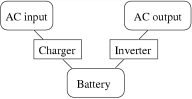
Offline: 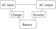
Line-interactive: 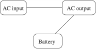
Example: a value of |
||||||||
|
battery test status |
1 byte |
|
|
When read, this register takes the following values:
When written, this register triggers the following events:
|
||||||||
|
audible alarm status |
1 byte |
|
|
A flag which determines whether the audible alarm of the UPS system is enabled.
My UPS allows this value to be set to any value in the range
|
||||||||
|
unknown |
1 byte |
|
|
I don’t know the function of registers |
||||||||
|
unknown |
1 byte |
|
|
|||||||||
|
unknown |
1 byte |
|
|
|||||||||
|
shutdown timer |
2 bytes |
|
|
This register holds the time, in seconds, until the UPS shuts down its load, or
|
||||||||
|
restart timer |
2 bytes |
|
|
This register holds the time, in minutes (not seconds!), until the UPS will restart its load, or Once this timer is set, it will be decremented once a minute; however, one cannot predict when the first decrement will happen (it happens between 0 and 60 seconds after the counter was set).
There is no way to stop a running timer: setting it to When the shutdown timer (register After a "final shutdown", flag During a "timed shutdown", flag
|
||||||||
|
unknown |
1 byte |
|
|
I don’t know the function of this register.
On my system, it takes value |
||||||||
|
AC input voltage |
2 bytes |
|
|
The current AC input voltage in 0.1V, or |
||||||||
|
AC input frequency |
2 bytes |
|
|
The current AC input frequency in 0.1Hz, or |
||||||||
|
temperature |
1 byte |
|
|
The current UPS temperature, in degrees C. My UPS does not actually implement this register, but the Bulldog software recognizes it. |
||||||||
|
AC output voltage |
2 bytes |
|
|
The current AC output voltage in 0.1V, both during on-line and battery operation.
Example: |
||||||||
|
AC output frequency |
2 bytes |
|
|
The current AC output frequency in 0.1Hz, both during on-line and battery operation.
Example: |
||||||||
|
unknown |
1 byte |
|
|
I don’t know the function of this register.
On my system, it takes value |
||||||||
|
loading level |
1 byte |
|
|
The current loading level in percent. |
||||||||
|
battery status |
1 byte |
|
|
Apparently identical to register |
||||||||
|
battery voltage |
2 bytes |
|
|
The current battery voltage in 0.1V.
Example: |
||||||||
|
battery level |
1 byte |
|
|
The current battery level in percent. |
||||||||
|
UPS status |
2 bytes |
|
|
This register holds the following flags. Since some of these conditions rarely occur, I am not sure whether my UPS implements all of them; anyway, the Bulldog Monitor recognizes them.
|
||||||||
|
battery status |
1 byte |
|
|
This register holds the following flags.
|
||||||||
|
unknown |
1 byte |
|
|
I don’t know the function of registers |
||||||||
|
unknown |
1 byte |
|
|
|||||||||
|
unknown |
1 byte |
|
|
|||||||||
|
unknown |
1 byte |
|
|
|||||||||
|
time remaining |
1 byte |
|
|
The estimated backup time until the battery runs out, in minutes. My UPS does not actually implement this register, but the Bulldog software recognizes it. |


Open Questions
-
There should be a way of initiating a soft shutdown without waiting for the batteries to run out.
-
Some information is still missing. There must be some flags which I have not observed during my tests, in particular, there should be flags for: Bypass Active, Fan Failure, Fuse Break, Inverter Bad, Charger Bad, Bypass Bad.
-
I am not sure how registers
06-0binteract with register0c.
Firmware Problems
Here are some areas in which the Belkin Universal UPS firmware could be improved:
-
add a command to shut down the load and put UPS into "awaiting power" mode. This should "flash" the load briefly (shut the load off and back on) in case AC power is already present.
-
allow shutdown timer and restart timer to be reset to
0to cancel a pending shutdown, rather than starting to count from 65535. -
allow timers to be set more accurately. Currently, by setting the restart timer to
1, it might expire anywhere between immediately and 60 seconds. In particular, it is not possible to set both the shutdown timer and the restart timer to1at the same time, because there is no guarantee that the first timer won’t expire before the second one is set. Thus, it is not possible to do a reliable timed shutdown of less than 2 minutes. -
Calculate battery level more accurately. Currently, this is a simple function of battery voltage, which means that the levels are interpreted very differently in battery mode than in line mode. This could be compensated for in software, but not reliably, as the battery levels might differ from one hardware/firmware version to the next.
Disclaimer
This document is distributed in the hope that it will be useful, but without any warranty. It is provided "as is", without warranty of any kind, either expressed or implied, including, but not limited to, the implied warranties of merchantability and fitness for a particular purpose. The entire risk as to the usage of information contained in this document is with you. Should the information prove incorrect, it may damage your UPS, your computer, or other equipment. You assume the cost of all necessary servicing, repair or correction.
In no event unless required by applicable law or agreed to in writing will any of the authors of this document, or any other party who may modify and/or redistribute this document, be liable to you for damages, including any general, special, incidental or consequential damages arising out of the use or inability to use the information (including but not limited to loss of data or data being rendered inaccurate or losses sustained by you or third parties), even if such author or other party has been advised of the possibility of such damages.