Network UPS Tools
Power Devices support
Table of Contents

This document describes the RS232 and USB communication protocols used in some UPS manufactured by Voltronic Power. It started as an “unofficial decoding work” and was later updated with protocol specifications kindly provided by Voltronic Power.

Hardware description

RS232

Baud rate

2400 bps

Data length

8 bits

Stop bit

1 bit

Parity

none

Cabling

9 pins female D-type connector - only 3 wires: TX, RX (crossed) and GND:
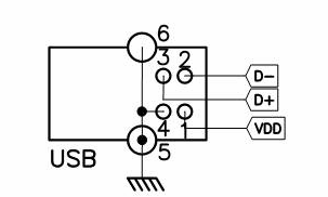
  COMPUTER         UPS
=======================
 RX  (pin 2) <---> TX
 TX  (pin 3) <---> RX
 GND (pin 5) <---> GND

USB

Communication

Serial over USB with cypress protocol

Cabling

USB scheme

General

  • All inquiry and control commands and UPS’s replies are terminated by <cr>.

  • Valid inquiry commands will get a reply terminated by <cr>:

    • In a UPS’s reply, unavailable or not supported data is filled with -.

    • In a UPS’s reply, if some data length is less than the definition, there will be enough # before the data to reach the expected length.

  • Accepted control commands are followed by action without any further reply.

  • When invalid control or inquiry commands are sent to the UPS:

    • P protocol:

      • if the command/query starts with T, the device doesn’t reply anything,

      • otherwise the device replies N<cr>.

    • T protocol:

      • the device replies N<cr>.

    • V protocol:

      • the device echoes back the invalid command/query.

Inquiry commands

By sending inquiry commands you can get the information you need from the UPS.

Note To get a valid reply, all data should be captured at the same time when UPS receives an inquiry command.
M

Query UPS for protocol.

Reply
X<cr>

Where X can be:

P protocol

QS

Query UPS for current status and data.

Reply
#AB C DE F G HI JKL M N O<cr>
Note One space (Hex: 0x20) is added between each field for data separation, but no space between multi-byte data.

Where:

#

Start byte

AB C

MCU-detected input voltage (high, A, and low, B, bytes, V rms) and input voltage ratio (C):

  • Input voltage (V) is obtained with the formula: AB * C / 51 / 256.

DE F

MCU-detected output voltage (high, D, and low, E, bytes, V rms) and output voltage ratio (F):

  • Output voltage (V) is obtained with the formula: DE * F / 51 / 256.

G

Output load level (%):

  • G is a percentage of rated load capability, not an absolute value.

  • If there is no output, the value must be forced to 0 %.

HI JKL

Output frequency time count (high, H and low, I, bytes, Hz) and output frequency ratio (high, J, medium, K, and low, L, bytes)

  • Frequency (Hz) is obtained with the formula: JKL / HI.

  • If the frequency is higher than 99.9 Hz, the value must be forced to 99.9 Hz.

  • If there is no output, the value must be forced to 0.0 Hz.

M N

MCU-detected battery voltage (M, V rms) and battery voltage ratio (N):

  • Battery voltage (V) is obtained with the formula: M * N / 510.

O

UPS status (8 bits):

  • O is one byte of binary information such as <b7b6b5b4b3b2b1b0>, where bn is either 0 or 1:

    Bit Logic 1 Logic 0

    7

    Utility fail

    Utility OK

    6

    Battery low

    Battery is not low

    5

    Boost or buck mode active

    Neither boost nor buck mode active

    4

    UPS fault

    No UPS fault

    3

    UPS type is line-interactive

    UPS type is on-line

    2

    UPS self-test in progress

    No UPS self-test in progress

    1

    UPS is in shutdown active status

    UPS is not in shutdown active status

    0

    Beeper is active

    Beeper is mute

<cr>

Stop byte

Note

To prevent confusion with control characters, in the following cases the original byte is changed:

Original Hex Changed to Hex

0x0D (CR)

0x28 0x00

0x11 (XON)

0x28 0x01

0x13 (XOFF)

0x28 0x02

0x0A (LF)

0x28 0x03

0x20 (SP)

0x28 0x04

Hence, if you find the ( character (Hex: 0x28) between start byte and stop byte, then you should consider also the next byte and check if they make up one of the aforementioned sequences: if so you have to use them both to get the original value.

For example, when PC sends the command QS<cr>, the data returned by UPS (in battery mode) is as the following hexadecimal:

Reply: 23 06 00 20 68 20 70 01 20 69 20 0C 20 61 A8 20 28 02 12 D0 20 D5 20 1E 20 89 0D
       -- -- --    --    -- --    --    --    -- --    ----- -- --    --    --    -- --
Id.:   #  A  B     C     D  E     F     G     H  I       J   K  L     M     N     O  <cr>

And it means:

Id. Hex value Meaning

#

23

Start byte

AB C

0600 68

Input voltage and ratio for input voltage → Input voltage = 0x0600 * 0x68 / 51 / 256 = 12.2 V

DE F

7001 69

Output voltage and ratio for output voltage → Output voltage = 0x7001 * 0x69 / 51 / 256 = 230.6 V

G

0C

Output load percent = 12 %

HI JKL

61A8 280212D0

Output frequency and ratio for output frequency [J = 0x28020x13 (see this note) → JKL = 0x1312D0] → Output frequency = 0x1312D0 / 0x61A8 = 50.0 Hz

M N

D5 1E

Battery voltage and ratio for battery voltage → Battery voltage = 0xD5 * 0x1E / 510 = 12.5 V

O

89

One byte of UPS status

Bit Value Meaning

7

1

Utility fail

6

0

Battery is not low

5

0

Neither boost nor buck mode active

4

0

No UPS fault

3

1

UPS type is line-interactive

2

0

No UPS self-test in progress

1

0

UPS is not in shutdown active status

0

1

Beeper is active

<cr>

0D

Stop byte

T protocol

QS

Query UPS for current status and data.

Reply
#AB C DE F G HI JKL M N O P<cr>
#..O, <cr>

Same meaning as in the reply to the QS query of P protocol.

P

UPS ratings (8 bits):

  • P is one byte of binary information such as <b7b6b5b4b3b2b1b0>, where bn is either 0 or 1:

    Bit Meaning

    7

    Nominal output frequency (Hz):

    • 1 → 60 Hz

    • 0 → 50 Hz

    6:5

    Nominal battery voltage (V):

    • 00 → 12 V

    • 01 → 24 V

    • 10 → 36 V

    • 11 → 48 V

    4

    Reserved

    3

    Reserved

    2:1:0

    Nominal output voltage (V):

    • 000 → 110 V

    • 001 → 120 V

    • 010 → 220 V

    • 011 → 230 V

    • 100 → 240 V

For example, when PC sends the command QS<cr>, the data returned by UPS (in battery mode) is as the following hexadecimal:

Reply: 23 01 02 20 65 20 73 01 20 65 20 00 20 60 00 20 12 C0 00 20 CC 20 3C 20 89 20 23 0D
       -- -- --    --    -- --    --    --    -- --    -- -- --    --    --    --    -- --
Id.:   #  A  B     C     D  E     F     G     H  I     J  K  L     M     N     O     P  <cr>

And it means:

Id. Hex value Meaning

#

23

Start byte

AB C

0102 65

Input voltage and ratio for input voltage → Input voltage = 0x0102 * 0x65 / 51 / 256 = 1.99 ~ 2.0 V

DE F

7301 65

Output voltage and ratio for output voltage → Output voltage = 0x7301 * 0x65 / 51 / 256 = 227.8 V

G

00

Output load percent = 0 %

HI JKL

6000 12C000

Output frequency and ratio for output frequency → Output frequency = 0x12C000 / 0x6000 = 50.0 Hz

M N

CC 3C

Battery voltage and ratio for battery voltage → Battery voltage = 0xCC * 0x3C / 510 = 24.0 V

O

89

One byte of UPS status

Bit Value Meaning

7

1

Utility fail

6

0

Battery is not low

5

0

Neither boost nor buck mode active

4

0

No UPS fault

3

1

UPS type is line-interactive

2

0

No UPS self-test in progress

1

0

UPS is not in shutdown active status

0

1

Beeper is active

P

23

One byte of UPS ratings

Bit Value Meaning

7

0

Nominal output frequency: 50 Hz

6:5

01

Nominal battery voltage: 24 V

4

0

Reserved

3

0

Reserved

2:1:0

011

Nominal output voltage: 230 V

<cr>

0D

Stop byte

V protocol

QS

Query UPS for current status and data.

Reply
(MMM.M NNN.N PPP.P QQQ RR.R SS.S TT.T U<cr>
Note One space (Hex: 0x20) is added between each field for data separation.

Where:

(

Start byte

MMM.M

Input voltage (V rms)

  • M is an integer number ranging from 0 to 9.

NNN.N

Input fault voltage (V rms)

  • N is an integer number ranging from 0 to 9.

  • Its purpose is to identify a short duration voltage glitch which causes off-line UPS to go to inverter mode. If this occurs, the input voltage will appear normal at query prior to glitch and will still appear normal at next query.

  • The input fault voltage will hold glitch voltage till next query: after query, the input fault voltage will be the same as input voltage until next glitch occurs.

PPP.P

Output voltage (V rms)

  • P is an integer number ranging form 0 to 9.

  • If there is no output, the value must be forced to 000.0 V.

QQQ

Output load level (%)

  • Q is an integer number ranging form 0 to 9.

  • QQQ is a percentage of rated load capability, not an absolute value.

  • If there is no output, the value must be forced to 000 V.

RR.R

Output frequency (Hz)

  • R is an integer number ranging from 0 to 9.

  • If the output frequency is higher than 99.9 Hz, the value must be forced to 99.9 Hz.

  • If there is no output, the value must be forced to 00.0 Hz.

SS.S

Battery voltage (V rms)

  • S is an integer number ranging from 0 to 9.

TT.T

Internal temperature (°C)

  • T is an integer number ranging form 0 to 9.

  • If the value can’t be obtained, the field must be filled with 25.0 °C.

U

UPS status (8 bits)

  • U is one byte of binary information such as <b7b6b5b4b3b2b1b0>, where bn is either the ASCII character 0 or 1:

    Bit Logic 1 Logic 0

    7

    Utility fail

    Utility OK

    6

    Battery low

    Battery is not low

    5

    Boost or buck mode active

    Neither boost nor buck mode active

    4

    UPS fault

    No UPS fault

    3

    UPS type is line-interactive

    UPS type is on-line

    2

    UPS self-test in progress

    No UPS self-test in progress

    1

    UPS is in shutdown active status

    UPS is not in shutdown active status

    0

    Beeper is active

    Beeper is mute

<cr>

Stop byte

For example, when PC sends the command QS<cr>, the data returned by UPS is as follows:

(208.4 140.0 208.4 034 59.9 12.8 35.0 00110000<cr>

And it means:

  • Input voltage is 208.4 V,

  • Input fault voltage is 140.0 V,

  • Output voltage is 208.4 V,

  • Output load level is 34 %.

  • Output frequency is 59.9 Hz,

  • Battery voltage is 12.8 V,

  • Temperature is 35.0 °C.

  • UPS type is on-line, UPS failed, AVR active and shutdown is not active.

F

Query UPS for ratings.

Reply
#MMM.M QQQ SS.SS RR.R<cr>
Note There should be a space character (Hex: 0x20) between every field for data separation.

The UPS’s response contains the following information fields:

MMM.M

Nominal output voltage (V).

QQQ

Nominal output current (A).

SS.SS or SSS.S

Nominal battery voltage (V):

  • SS.SS when less than 99.99 V;

  • SSS.S for 99.99 V upwards.

RR.R

Nominal output frequency (Hz).

For example, when PC sends the command F<cr>, the data returned by UPS is as follows:

#220.0 003 12.00 50.0<cr>

And it means:

  • Nominal output voltage is 220.0 V,

  • Nominal output current is 3 A,

  • Nominal battery voltage is 12.0 V,

  • Nominal output frequency is 50.0 Hz.

Control commands

By sending control commands you can control the UPS.

T

Invoke a 10 seconds battery self-test and then return to utility.

  • If battery low occurs during testing, UPS will return to utility immediately.

  • Only when UPS is in line mode and battery voltage is not less than 13V/pcs, the command is executed.

S<n>R<m>

Shutdown (and restore): shut UPS output off in <n> minutes, wait <m> minutes and then turn on UPS output again.

  • The UPS output will be off in <n> minutes, even if utility power is present.

  • If battery low occurs before <n> minutes, the output is turned off immediately.

  • After UPS shutdown, the controller of the UPS monitors utility power: if utility is recovered, the UPS will wait for <m> minutes and connect the utility to output.

  • When <m> minutes expire, if utility has not been restored, the UPS will wait until utility is restored.

  • If UPS is in shutdown waiting status (while <n> minutes elapse), the C command can cancel the shutdown command.

  • If UPS is in recovery waiting status (while <m> minutes elapse) and mains is present, the C command can turn on the UPS output, but UPS must be held off at least 10 seconds.

  • <n> is a number ranging from .2, .3, …, 01, 02, …, to 09.

  • <m> is a number ranging from 0000 to 9999. If it is 0000, output won’t be turned on, and, if control power can be shut off, then it is turned off immediately.

C

Cancel the S<n>R<m> shutdown command.

  • UPS only accepts this command when the S<n>R<m> command has not been completed.

  • If UPS is in shutdown waiting status (while <n> minutes of the S<n>R<m> command elapse), the shutdown command is cancelled.

  • If UPS is in recovery waiting status (while <m> minutes of the S<n>R<m> command elapse) and mains is present, the UPS output is turned on, but UPS must be held off at least 10 seconds.

Q

Toggle the UPS beeper.

  • When AC power fails, UPS will generate a warning beep to inform the manager. The manager can toggle the warning beep by sending this command.

P protocol

CT

This command, though supported by devices that implement the P protocol, does nothing. As a consequence of that, when this command is sent to the UPS, the device doesn’t reply anything (since the command is supported and not invalid, the UPS doesn’t return N<cr>).

Known problems

The following issues have been reported by some people with ‘V protocol’ devices:

  • S<n>R0000 command is known to work as expected (i.e. turn the load off indefinitely) only if mains is present, otherwise, as soon as mains returns the load gets powered.

  • After issuing a S<n>R<m> command, the UPS won’t wait <m> minutes before powering on the load, provided that the following conditions are met:

    • if the load has been previously (no matter how long before) powered off through S<n>R0000 command and powered on through C command and

    • if AC wasn’t cut after issuing the S<n>R0000 command (i.e. the UPS didn’t turn itself off) and

    • if there’s a power outage after issuing the S<n>R<m> command.

    In this case, as soon as mains returns the load gets powered.

Revision history

Rev. Date Description Author

1.0

01/2014

Initial release

Daniele Pezzini

2.0

11/2015

Update the document adding information provided by Voltronic Power

Daniele Pezzini